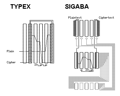
Despite the fact that the Enigma never enciphered a letter as itself, thereby making it easy to align probable plaintext with an intercept, several other rotor machines were based on the Enigma.
W. F. Friedman devised Converter M-325. It was similar to the Enigma, except that the rotor nearest the reflecting rotor, rather than the rotor farthest from it, was the fast rotor. This produced a machine that did not need a plugboard to be reasonably secure.
The British cipher machine during World War II was the Typex. Its rotors were notched several times for frequent and irregular motion. Three rotors moved, and the farthest of them from the reflecting rotor was still the fast rotor. But there were two other rotors beyond the fast rotor, and they acted as a plugboard replacement.
Some models of the Typex had two concentric sets of 26 contacts. According to those who have had the opportunity to examine surviving specimens of this machine, they were not used for the obvious purpose of providing a return path for electrical current, thus allowing the unique weaknesses of the Enigma design to be avoided.
Despite this, I still wonder; there is a simple way, using dummy rotors connected by cables, to turn a SIGABA into a plain Hebern machine. As the SIGABA and the Typex were made to interoperate by means of accessories which turned them into the "Combined Cipher Machine", it makes sense to conclude that the second set of contacts was used as a return path on the Typex, since then suitably wired rotors with some sets of contacts wired without scrambling could allow Hebern type operation of such a machine as well, thus facilitating this particular method of interoperation. Although the fact that the fast rotor is on the entrance side (like an Enigma, unlike an M-325) makes it more difficult to turn a Typex into a Hebern machine with the fast rotor in the middle, it is not impossible: an auxilliary wiring harness, with dummy rotors, is also required as with the SIGABA, and the reflecting rotor is one of those that has to be replaced. The following diagram shows a principle that may have been used:

As the details of the actual CCM are available, no doubt I will soon be hearing if my reconstruction is near the mark or not. As only three rotors aren't much, the actual CCM may have been somewhat more complicated, for example by including entry and exit plugboards to replace the two stators in a real Hebern five-rotor machine.
As the Typex is said to have very closely resembled the Enigma, I had assumed that it had a "650 break" as well, and this would have further complicated interoperation with the SIGABA. However, since the Typex used heavily multinotched wheels, such a gearing arrangement would have shortened its period considerably, so perhaps that problem did not arise. (It's even possible there was a lever somewhere to choose with!)
On some later models of the Typex, the two entrance rotors also moved. This is merely a speculation on my part, but one simple way in which they could have been caused to move is this: the entrance rotor would be the slow rotor, the next one the medium, and the same notches in the wheels that caused the regular carry would also cause movement of the wheels on the entrance side, but the ratchet wheels would be displaced. So, if the positions B, G, J, M, O, R, T, V, and X caused the original medium wheel to move when the fast wheel reached them, and the original slow wheel to move when the medium wheel reached them, then perhaps the positions Z, E, H, K, M, P, R, T, and V, each two positions earlier, would cause movement on the other side of the fast rotor. Or another row of notches could be present on the wheels, and the number of notches in that row could very well be even, since the ordinary rotor motion would already be providing the maximum period. No such motion, however, unlike the original motion with those two rotors as stators, or better yet a motion resembling that of the Converter M-325, would allow easy interoperation with a SIGABA using dummy rotors by emulating a Hebern machine, basically the lowest common denominator of the two machine types.
Some time after World War II, Switzerland, which had been using a version of the Enigma for its own communications, designed its own significantly improved cipher machine based on the Enigma, the NEMA (for Neue Maschine, not National Electrical Manufacturers Association). Recently, a computer program simulating its operation, accompanied by a description of the machine, became available. One of the program's authors, Frode Weierud, has a forthcoming article in Cryptologia about the machine.
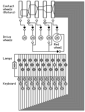
It used lamps to indicate the letters it produced as output, and physically it looked like a metal box with a sloped front in which a typewriter keyboard was sunk. Recently, examples have become available on the open market, at prices considerably below those of World War II Enigmas.
The device had four rotors, plus a reflecting rotor, all of which (including the reflecting rotor) moved during encipherment. However, it had the appearance of having ten (rather thin) rotors. This was because each rotor was manually adjusted by means of a flange on its left with 26 segments labelled with the letters of the alphabet, and bore on its right a ring of appearance similar to that flange, but which contained a notched gear. Each rotor's movement was controlled by the ring to its right; when a notch on the ring came into position, its corresponding rotor did not advance for the current letter being enciphered. In addition, the ring on the entrance rotor, towards the right of the rotor bank, was distinctively colored (it was red) and had a second notched gear on it. This gear, when a notch on it came into position, prevented the second and fourth rotors, and their corresponding rings, from moving. Usually, all the rings would move with every character enciphered.
Thus, the NEMA had a period of 17,576 letters, each ring-rotor pair having a period of 676. If the red ring had stopped only two other rings, and not their corresponding rotors as well, the period could have been 26 times longer. In any case, it has a large number of initial settings, and a very irregular rotor movement, bettered only by that of the SIGABA (although the Enigma A and Enigma B also had a rotor movement that is more irregular than usual). Note that the diagram, for simplicity, shows the mechanics of the rotor movement by lines which may suggest electrical wires; actually, the result was achieved mechanically. Also note that the wheels with notched gears, although concentric on the same shaft as the rotors, are shown in the diagram in a row below the rotors, using the usual diagram symbol for pinwheels.
And, during the sixties, an Italian firm, O.M.I., offered a version of the Enigma with seven rotors. But it embodied an ingenious idea for providing security in a machine sold openly without requiring customers to rewire their rotors. The rotors came in two pieces, both with scrambled wiring, that the customer could interchange and rotate to form the rotor set to use.
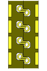
It would be a little harder to do this with rotors of the Hebern type, if one wished to take full advantage of the fact that both sides of these rotors are identical, but it could still be done using androgynous connectors positioned in alignment with the centers of the contacts, as shown below:
An interesting web site in Germany, which no longer exists, described several cipher machines from behind the Iron Curtain. Three of them were described in enough detail (which I tried to make out as best I could, not understanding German) that I found their mention of interest.
The T217, or ELBRUS, is an electronic cipher machine, having at least a superficial external resemblance to the early electronic cipher machines used by the United States (as those machines are, as far as I know, still classified, I have no knowledge of whether the resemblance is more than superficial). A linear-feedback shift-register generator feeds a longer shift register, and bits from that are selected under the control a key cassette to go into combinatorial logic to produce bits for stream cipher use.
The M105 uses a principle I don't quite understand yet: 5-level code characters are converted to a 12-bit form, then XORed with a key tape, then converted back down to 5-bit form. It isn't quite clear to me how transformations more involved than an XOR can actually be accomplished by this principle, particularly when decoding is also performed by precisely the same method. However, such a machine could work by cheating; for example, the 5-bit character
abcde
could be converted to
abcde0000000
to be enciphered, and then the 12-bit result of being XORed with the key tape could be converted to 5 bits by taking the first 5 bits, performing a nonlinear operation controlled by the last 2 bits, and then XORing with the second 5 bits. To decipher using the same key tape, the 5-bit ciphertext character
pqrst
would simply be converted to
00000pqrst00
before the XOR with the key tape. Even something like that, particularly if a plugboard can be used to scramble the 12 bits from the key tape, might not be entirely silly. Also, if the nonlinear transform controlled by the last 2 bits leaves something invariant, that, rather than 0, could be put in the last 2 bits. For example, if the last 2 bits are used to choose between different ways of transposing the 5 bits of a character, for encryption the parity of the plaintext character could be placed in one, or both, of those bits before the XOR, affecting which bit transpose is used.
For decryption, the parity of the ciphertext character after being XORed with the five bits for that purpose on the tape, XORed with the parity of the five bits that will later be XORed to form the plaintext character, will produce the parity of the plaintext character before the bit transpose (affected by that parity) is known.
And, finally, the M125, or the Fialka, is described on his site, which is why I am mentioning his site on this page: it is a variation of the Enigma.
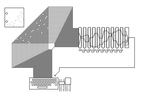
It enciphers a 31-character alphabet. A punched card is used to perform the function of the Enigma plugboard, but for only of 30 of the 31 symbols enciphered. The punched card has been described to me as square, with two centering holes, and with the regular punched holes only below a diagonal on the card. This suggests to me that each hole position controls a double-pole double-throw (DPDT) switch, determining if two lines in a folded crossbar pattern are crossed.
There are 10 highly multinotched rotors, and they have fixed contacts on one side and spring-loaded contacts on the other, like those of the Enigma.
Now, these 10 rotors all have 31 contacts on each side. There is also a reflecting rotor, but how can a reflecting rotor with an odd number of contacts work?
One contact of the reflecting rotor, instead of being connected to another contact, is connected to a circuit that causes the machine to encipher the input letter as itself. Note, however, that the machine's cipher is fully reciprocal.
Like the Typex, we have an Enigma with both multinotched rotors and a plugboard; British cryptanalysts working on the Abwehr Enigma on the one hand, and the Army and Navy Enigmas on the other saw that to be an effective combination. This may not be terribly surprising, as there was Soviet penetration of the British Ultra effort during World War II. The patch panel, like the Uhr Box, avoids the problem of the plugboard substitution being reciprocal in itself.
Although the machine is connected to 5-level tape equipment, instead of enciphering normal 5-level code (leaving, perhaps, the all-zeroes character unenciphered) the German-language version of this device omits the letters W, X, and Y, and uses J to represent the space (thus printing a space when deciphering, and a J when enciphering), leaving room for the digits from 2 through 9 in the character set. As Russian has a 32-letter alphabet, presumably the original Russian-language version did not include digits in its character set.
My initial attempt to reconstruct the Fialka from the information I had found resulted in a somewhat different machine, with its own features of interest.

In the a block diagram I saw, there were three signals going from the reflecting rotor to a transistor symbol. I thought that perhaps this meant that three contacts were wired in a loop, with diodes going from one to the next, in rotation. As a DC current is used to go from the keyboard to the rotors and back to the output mechanism, this can mean that A becomes B, B becomes C, and C becomes A. (However, there is nothing to prevent the current from going through two diodes in a row. This can be avoided by the use of resistors or multiple diodes, and a suitable choice of voltage threshold, or by a simple transistor circuit.)
That would mean the cipher of the machine as a whole would not be quite reciprocal, but no letter could represent itself. The easiest way to reverse the action of such a circuit during decipherment would be simply to reverse the polarity of DC current through the machine.
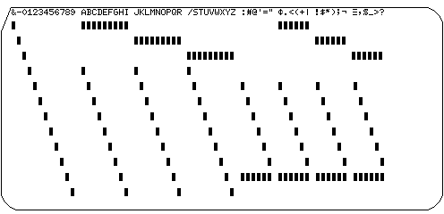
The fact that the punched-card "plugboard" affected only 30 of the machine's 31 characters was baffling to me, and implied some sort of external constraint. As I assumed a simple crossbar arrangement for card sensing, to minimize parts count, the fact that a standard 80-column card has over 900 holes in it meant that it could indeed control a 30 by 30 crossbar patch panel. (One needs 961 hole positions for a 31 by 31 crossbar patch panel!) The diagram shows a possible arrangement for the crossbar circuitry that uses the first 75 columns of the card, and which, by taking into account the zone and digit positions of the card, allows key cards to be produced with conventional punched card equipment, using only &, -, /, and the digits and the upper-case letters.
Perhaps the construction I reached through speculation will be helpful to amateur builders intending to build a replica of the Fialka at home, but with the use of more standard parts, even if it departs from the historical reality.
The following diagram is provided for those who aren't familiar with the code used on the 80-column punched card:

or, if that diagram is difficult to understand, here is a more explicit one:
Gordon Welchmann, the inventor of the diagonal board, has commented that it would have been possible, but difficult, to design an Enigma that did not have the feature of being unable to encipher a letter as itself.
Obviously, the simplest method to avoid this problem with the Enigma would be to revert to sending the signal through the rotors in only one direction, as with the Enigma A and Enigma B, or as with the original Hebern machine. But if one wanted to avoid having to switch a large number of wires when changing from encipherment to decipherment, or if one felt it useful to have the signal going through the rotors twice instead of just once, how would an Enigma not having this problem be designed?
One can begin by merely changing the labels which are over the indicating light bulbs. If the light bulb that is on the circuit with the Q key is now labelled B instead of Q, then it is B that the letter Q will not be enciphered as.
But then one would have to have one wiring for encipherment, and a different wiring, either selected by a large and complex switch, or by constructing enciphering Enigmas and deciphering Enigmas.
One way to avoid the problem would be to replace the plugboard of the Enigma with two switchboards, one connecting the keys to the machine, and one connecting the lamps to the machine. Then one could select any wiring configuration for encipherment, and its counterpart, with lamp and key wirings exchanged, for decipherment.
Could a suitable choice of new labels for the light bulbs allow a simpler solution, one that involved a lesser change to the way the Enigma worked? One possibility would be, given the keys are connected to the rotor contacts in alphabetical order, to label the light bulb connnected to the A key with N, the light bulb connected to the B key with O, and so on. Then, if the setting rings are labelled with two alphabets similarly displaced, in contrasting colors, and the gear teeth by which one ring advances the next are so arranged that if a tooth is at one position, there is also a tooth at the position diametrically opposite (shortening the period, because all the rotors must now have an even number of teeth), one could indeed have a machine that behaved almost exactly like the Enigma.
However, the fact that the letter A can now never be represented by N, instead of never by A, is just a fixed substitution that would soon be discovered, and then it would cause no real difficulties for the cryptanalyst. A normal Enigma plugboard would not change this: and the sockets on it would also have to be labelled in two colors, as the plugboard wiring would have to be displaced 13 positions to decipher.
Another thought would be, instead of having two switchboard-type plugboards, where a set of 26 sockets is matched by 26 plugs from within the Enigma, to have a second plugboard of the regular Enigma type in a single Enigma. In addition to the one between the rotors and the lamps and keys both, the additional plugboard would be between the lamps and the keys. The reciprocal nature of the plugboard substitution would not be a problem, and would in fact allow the same wiring to serve for encryption and decryption. This arrangement is illustrated below:

However, it wouldn't quite work as illustrated. Although the rotor substitution and the plugboard substitution are both reciprocal, that does not mean that they commute. But a more complicated wiring based on this principle would be possible, such as placing the rotors on the lamp side for decipherment; this would require a bank of 26 relays to simulate the effect of the switches in the keyboard.
One simple way to make this work, with some limitations, is this: for encipherment, use only the plugboard between the lamps and keyboard. For decipherment, also use the regular plugboard, and wire it in the same way as the plugboard between the lamps and keyboard. This works because plugboard wirings are reciprocal.
The basic problem of this sort of arrangement is that the rotors are connected to the keyboard and not the lamps in an Enigma, hence a permutation between the keyboard and lamps disrupts the relationship between the rotor contacts and the lamps and keys that makes decipherment possible when it is reversed for decipherment. Could an Enigma be modified so that the rotors were connected to the lamps? Yes, if each lamp were shorted with a diode:
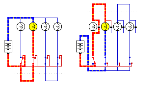
This diagram shows the flow of electricity in an Enigma. On the left, a simplified diagram of the Enigma is shown. Wires at a positive potential are red, wires at a negative potential are blue, and wires carrying current are shown thicker with yellow symbols indicating the direction of current.
On the right, the arrangement involving diodes needed to allow the rotors to be connected to the lamp side of a modified Enigma is illustrated. Current that pressing a key allows to flow goes first through the shorting diode belonging to the lamp with the same letter, then through the rotors, and on its return trip lights the correct lamp, since it is going the other way, and cannot be shorted by that lamp's diode.
Suitable switching circuitry, allowing either arrangement to be selected, and reversing other connections, would allow a two-plugboard Enigma of the type shown above to even have an Uhr box connected at either or both plugboards.
Next
Chapter Start
Skip to Next Section
Table of Contents
Main Page